
CNC Turning for Custom Hydraulic Components
CNC Turning for Custom Hydraulic Components
There are times when you have a component or a subsystem within a hydraulic system that needs to be replaced. Buying the new part may be the smart move in some instances, but that solution becomes less attractive when there are long lead times for delivery, the part is hard to locate, it is no longer supported by the manufacturer, or the replacement options available are not a good fit for your particular system. Many hydraulic parts and components — from entire cylinder assemblies to a single piston in a hydraulic pump — can be CNC turned quickly and inexpensively.
Machining
Machining processes are metal removal processes that depend on cutting and grinding operations to remove unwanted material from the workpiece in order to achieve a final shape. The three basic machining processes are milling, turning, and grinding. All three can be leveraged to achieve a final part that meets strict tolerances for dimensions, flatness, roundness, surface finish, etc.
The difference between milling and turning is quite straightforward. In milling, a rotating cutting tool is held stationary while the workpiece is moved relative to it in a three-dimensional plane. In turning, the cutting tool is moved in a three-dimensional plane while the workpiece is rotated. Additionally, turning focuses on the machining of rotational parts. While milling can be used interchangeably with turning for some processes, milling is simply not as well adapted to creating rotational parts.
Turning
As just alluded to, turning is ideal for manufacturing parts with rotational features such as tapers, steps, chamfers, grooves, and contoured surfaces. It is also often used as a secondary machining process to achieve certain part features or meet strict dimensional or geometric tolerances. Turning is commonly used to make hydraulic components including pistons, rods, cylinders, barrels, end caps, plain bearings, and shafts.
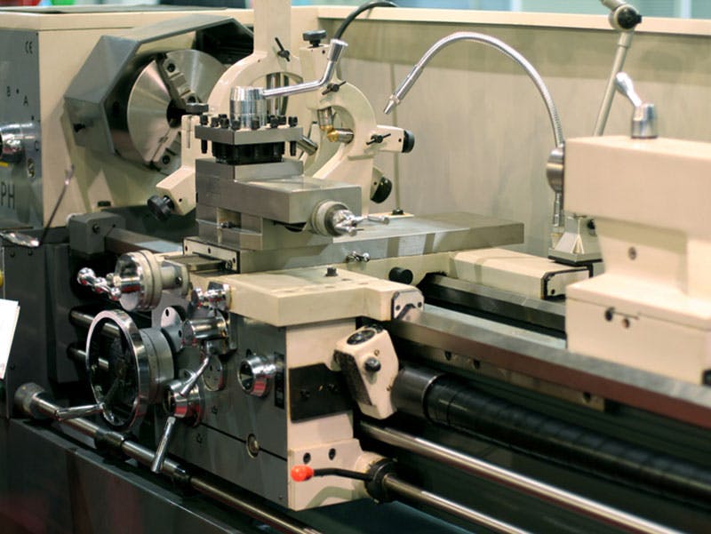
While milling is done with a milling machine, turning is accomplished with a lathe. The workpiece is clamped in a holder that is connected to the spindle and motor to achieve rotational motion. Some lathes have a turret that can hold multiple cutting tools at the same time in order to make tool changes easier. Most cutting tools are made from HSS steel, carbon steel, carbide, or cobalt high-speed steel. These tools need to be periodically sharpened to maintain their ability to cut and can be broken if the correct cutting parameters are not chosen.
External Turning Operations
In basic external turning processes, the workpiece is rotated as a single-point cutting tool is moved either axially or radially with respect to it. In basic turning, the tool can be moved axially along the length of the part to achieve steps, chamfers, tapers, and contoured surfaces. It can also be moved radially with respect to the free end of the part in a process called facing (which is typically done to achieve a certain level of flatness). A length of the workpiece can be cut off (or parted) using a method very similar to facing. Threading and grooving are also external turning operations. They depend on both the radial and axial movement of the cutting tool. The major difference between the two is that threading requires a more specialized tool to achieve the correct shape for the threads.
Internal Turning Operations
Turning also makes internal cutting operations possible. All of these operations — drilling, tapping, boring, and reaming — begin at the free end of the workpiece. Drilling is used for cutting a hole that is the same diameter as the cutting tool, while tapping is used to create internal threads and, like the external threading process, requires a special cutting tool. Boring typically follows the drilling process to further enlarge the hole and can also be used to achieve internal steps, chamfers, contours, and tapers. Reaming can also follow drilling and is used to achieve a better internal surface finish or a more accurate diameter.
Key Parameters in Turning

In milling, there are three critical parameters: speed, feed, and depth of cut. In turning, the speed refers to the rotational speed in rotations per minute (rpm) of the rotating part while the feed is the speed at which the cutting tool is moved. The depth of cut is what depth of material is removed during each pass of the cutting tool. Selecting the right speed, feed, and depth of cut is critical to the success of the turning process and has a major effect on not just the accuracy, precision, and surface finish but also the grain structure of the part near the cutting area. Issues such as friction, heat generation, conductivity, and chip formation, must be taken into account.
Turning a Part
Manufacturing a single part will involve several different processes. For example, metal tube stock may be procured to fabricate a new barrel for a hydraulic cylinder system. First, the correct length of tube will need to be cut off in a parting operation. Next, external turning operations will reduce the exterior of the workpiece to the correct diameter and shape, and any chamfers will be added. External threads may also need to be added, and all of these operations require different tools and cutting parameters.
Then come the internal operations, such as boring to increase the internal diameter of the workpiece, reaming to achieve accuracy, and tapping — each requiring a different tool and slightly different speed and feed settings.
CNC Turning
The traditional approach to machining involves manual operation, where a trained machinist sets the critical parameters for each of the operations (speed, feed, and depth of cut) and controls the motion of the cutting tool relative to the workpiece. CNC, which stands for computer numerical control, uses computerized control systems to automate much of the machining process. CNC lathes have the necessary control systems and hardware to interact with CNC software.
At the core of any CNC software system is the M&G code, the programming language that converts the various steps of a turning process into something that the CNC lathe can understand. This code allows the machinist to set the correct machining parameters, configure the coordinate system for the process, and develop the step-by-step instructions for each process. These instructions include positioning of the tool, feeding the tool into the workpiece at a specific speed, and specifying the cutting path for the tool.
M&G code also supports functions such as automating tool changes, turning on and off compressed air to blow chips away, and activating coolant spray to conduct heat away from the cutting surface.
Also, note that CNC technology can be combined with CAD/CAM (computer-aided design/computer-aided manufacturing) packages to suggest the sequence of processes needed and generate the tool paths based on a 3D model of the part. Most modern CNC turning facilities use CAD/CAM to speed up the development of M&G code, although a skilled machinist can develop the code by hand.
Materials Used in Turning

Most turned parts in the context of hydraulics are made from metal, and turning is compatible with alloy steel, stainless steel, carbon steel, aluminum, copper, nickel, titanium, and even cast iron. However, the harder the material of choice, the longer it will take to machine and the more wear the cutting tools will experience. Turning materials like cast iron will take experience and skill on the part of the machinist to achieve smooth and accurate cuts, even with CNC and CAD/CAM equipment.
However, metals aren’t the only materials that can be turned. Polymers (including elastomers, thermosets, and thermoplastics) can also be turned with great precision, accuracy, and speed. Polymers or wax may be used to fabricate prototypes to check for size and program accuracy before the final metal workpiece is turned. Developing a prototype this way saves time and avoids costly mistakes. Note that ceramics and composite materials can be turned also, but may require a different type of tooling than metals.
Benefits of CNC Turning
There are several benefits to CNC turning, including:
- Shortened lead times due to the automation of the turning process
- Faster response to design changes
- Higher accuracy and precision due to increased control over cutting speeds, feeds, and tool paths
- Cost-effective short production runs
- Customized parts and components
CNC Turning for Custom Hydraulic Parts
CNC turning parts for repairs can be a very cost-effective approach, even for complex fluid control components. It is often used in the manufacturing of rods, cylinders, hose hardware, and components for pumps and hydraulic motors. CNC turning can be used for small parts and large parts alike. Fabrication of these parts is made possible by the high levels of accuracy, precision, and tolerances that can be done with correctly configured CAD/CAM and CNC systems. Prototypes can cut in softer material like wax to verify the M&G code before the final part is made and any necessary changes can be implemented quickly. And keep in mind that machining a limited number of items can be more cost-efficient than replacing an entire system.
MAC Hydraulics
At MAC Hydraulics, we have state-of-the-art machining and welding equipment in our extensive fabrication department. Our highly-skilled and experienced craftsmen have the tools and software to fabricate custom hydraulic parts and remanufacture components. This includes CNC milling, CNC turning, and welding capabilities that make it possible for you to get the high quality, custom parts that you need. This is in addition to our other services, such as on-site maintenance and repairs, hose replacement, testing and certification, and building custom units. Contact MAC Hydraulics today to find out what we have to offer your hydraulic systems.
